Home
How To

Cam Sensor Installation and Adjustment
Two Notes:
1) The cam sensor has nothing to do
with ignition timing. That is controlled by the chip. It locates
cylinder #6 so that both injector pulse and ignition spark will be on the
correct cylinders. Rotating it like a distributor does not affect actual
spark timing. It is either right, or it is wrong.
2) If you have bought the
Casper's replacement cap with the led in the top. Use the instructions
that came with it instead of the below.
This method is proposed by Chuck Leeper of Cody
Motorsports. It uses the
Caspers Cam sensor tool rather than a volt meter
but the technique is valid for either.
- Take a piece of masking tape and make two marks 1.45" apart.
- Go to the harmonic balancer and position one mark on the top dead center
notch with the other mark positioned
counterclockwise from the first.
This corresponds to 25 degrees ATDC. Make a mark on the balancer at this
point.
- Turn the crankshaft on clockwise until this mark lines up with the
pointer. Note, it is important that the crank is on Top Dead Center and
then 25 degrees past TDC. Remember that the cam turns at half the
speed of the crankshaft and merely turning the crank until the point lines up
with the pointer only assures you a 50% chance of being correctly on the 25
deg TDC mark. TDC is found when the notch on the balancer lines up
with the timing pointer on the cover and both valves on cylinder # 1
are closed (Number 1 plug is the front plug on the
drivers side). In order to not have to pull the valve cover, I remove the
spark plug and start turning the crank clockwise until I feel a puff of air
come out the plug hole. This will be the compression stroke and I then
continue turning the crank until I reach the 25 ATDC point.
If you
don't get this right, you will not like the way it runs as it will be spraying
fuel 180 degs out of phase.
- Take the camshaft positioning sensor and turn the gear until the dot
on the gear is aimed toward the passenger fender when the the wires on the cap
are pointed toward the driver's side headlight.
- Install the sensor into its hole. It helps to lube the O-ring a bit
so the sensor will slide into place. Note that as the sensor is
inserted, the gear on the bottom will mesh with the gear on the cam and then
the end of the sensor drive must line up with the end of the oil pump drive
shaft. If the shaft and the sensor drive don't line up correctly, the
sensor will not go all the way down. If you felt the two gears mesh,
just bump the engine over while gently holding the sensor down. When the
sensor turns enough to line up with the drive shaft, it will drop down into
place.
- Install the hold down leaving the sensor just loose enough to rotate when
you turn it with your hand.
- Using the
Casper's cam sensor tool, plug it into the cam sensor harness.
- Turn the cam sensor clockwise until the LED on the tool goes out, then
turn the sensor counterclockwise until the LED comes back on. I suggest
turning the sensor about 1/8" to 1/4" further CCW from this point before
tightening the hold down clamp. The LED should still be lit, however*.
- If you don't have Casper's tool,
Here is a method of adjustment using your volt meter. Also, at the
bottom of the page will be a picture from the factory manual on using a
voltmeter.
For an in depth discussion of the cam sensor function, go
Here.
*Rotating
the sensor CCW after the initial setting point may be folklore, but,
many have found it to make cars with larger than stock cams run a bit
better and reduce the tendency toward detonation. The theoretical
guys say it cannot help...but, I have seen it more than once so I do it
on my cars.
Lately, I have seen it fix part throttle, low boost miss problems in cases
where the vertical play in the shaft was causing the reluctor window to get out
of synch with the fuel timing window. The correct way to fix this problem,
obviously, would be to reduce the vertical play in the shaft.
The following pictures were provided courtesy of Chuck Leeper, Cody
MotorSports.
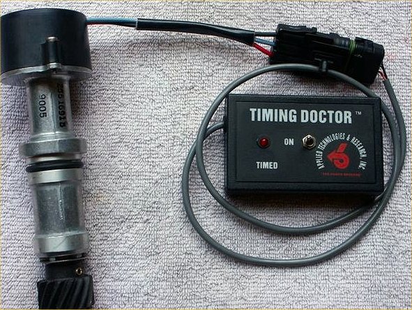
This picture shows the cam sensor drive and cap assembled with
the
Cam Tool plugged in. This one is from
ATR.
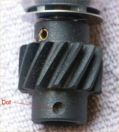
Dot goes toward the passenger side fender when inserting drive
assembly. Remember, engine must be sitting at 25 degs ATDC!
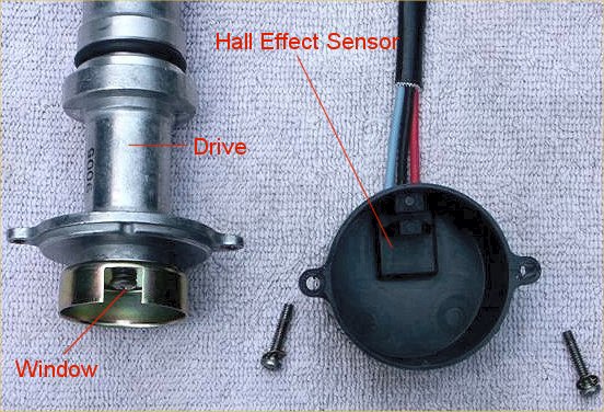
Window will be pointing toward the drivers side fender when
inserting drive.
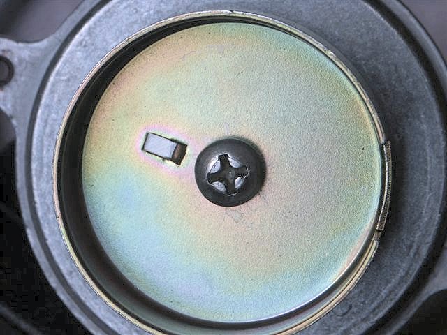
Top view of drive assembly. The wheel must be pinned into
place so that it cannot rotate versus the drive gear. If the wheel moves,
it will screw up the fuel timing and the car may not start, or, it will run very
badly.
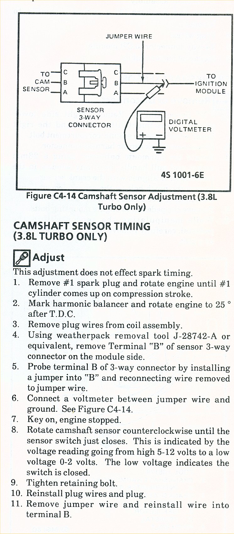
Voltmeter procedure from the shop manual below.