
Basics
O2 sensor Mass Air Flow Sensor (MAF) Open Loop-Closed Loop Throttle Position Sensor Adjustment IAC Adjustment Cam Sensor Crank Sensor EGR Wastegate Solenoid Fuel Injectors Fuel Pumps Factory Fuel Pump Relay Fuel Pressure Regulator Detonation Detonation Sensor False Detonation Boost Control
The oem Oxygen sensor is a narrow band, or switching, sensor. Here is a graph that depicts voltage versus Air/Fuel Ratio. As can be seen, the output is not linear at all and it is virtually impossible to convert the voltage to a reliable A/F. It is meaningful at 14.7-1 which is the way it was designed.
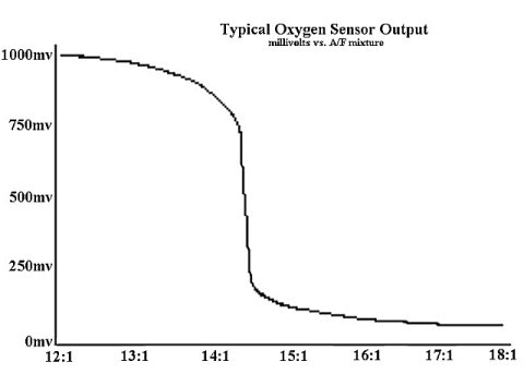
The sole function that the oem sensor performs is to signal the ecm if the exhaust gas passing over the sensor is either rich or lean with the stochiometric A/F point of 14.7 being the dividing line. It simply acts as a switch that is used to correct fueling at part throttle to optimize mileage and emissions. It is NOT used to determine fueling at wide open throttle.
Not only is the sensor extremely insensitive on either side of stochiometric, it is also affected by exhaust gas temperature and pressure. As the sensor heats or cools, its output voltage changes even if the A/F ratio does not.
Trying to use the output voltage of the stock sensor to determine an optimum A/F ratio for a given car is essentially a futile exercise due to the very nature of the sensor and the changes that may be incurred with temperature swings.
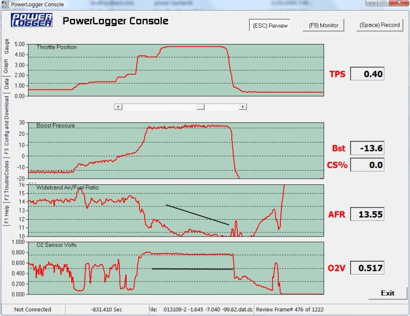
Below is a log comparing the output from a wideband O2 to the output from the factory narrow band. During the period under boost there is more than a 20% variation in actual air to fuel ratio when the factory O2 voltage is basically flat. Something to think about.
Note that when someone says the O2s should be 800 or another magic number they like, they are referring to wide open throttle O2s at the top of 3rd gear. My experience has shown that Alky Injection has allowed me to safely run lower O2's on the oem sensor. I use a wide band for fine tuning though.
Let me say, however, that thousands of people have gotten by for 20 years with the oem narrow band sensor. If one is careful to stay out of timing retard, then one is okay. On the other hand, if one has a modern programmable chip with options to tweak the A/F at various parts of the rpm range, and/or in different gears, then the WB should be a help in optimizing performance. After years of playing with wide bands, I am no longer as adamant that they are a necessary tool for the average guy with the average car-particularly those that are spraying alky. Why? One can spray a little alky along with a lot of gas, or spray a lot of alky and less gas and both combinations can end up with the same A/F ratio, but the results can be totally different due to the different characteristics of each mixture. Given the variety of possibilities between the two extemes, one can not rely on a given wideband A/F ratio to always be the best, or the safest. Lately, I have seen several cases where a fuel pump was gradually dying over a period of time and alcohol was very gradually being added to fix the "detonation problem" that kept popping up. The wideband number looked good, but, the oem looked way rich. A new fuel pump fixed the problem in each case. In none of the cases had the owner checked the fuel pressure because the wide band said all was good. Yes, the oem O2 is totally non-linear. But, it is very repeatable on non leaded gas so pay attention to it. When the relationship between the oem and the wb changes-figure out why.
In normal driving the O2s should be bouncing back and forth across stochiometric which may be either 0.441v or 0.500 v depending upon which scan tool one is using (Scanmaster and PowerLogger use .441 v). Most modern chips use a form of open loop at idle and the O2's will be relatively stable at idle. Most do go back to closed loop operation off idle.
Note that a properly functioning O2 sensor is required for proper performance and mileage from any chip that is closed loop like the factory chips. This means virtually all chips other than the MaxEfforts, some of the Turbotweaks, and some of Bob Bailey's. I am referring mainly to Speed Density chips in this case although there are now closed loop chips that can be driven with a wideband, as well.
O2 Cross Counts-Cross counts are what you watch to make sure the O2 is still working correctly. A good sensor will increment counts at least 8-12 (as a minimum) per ScanMaster frame. That would be about 30 frames on the PowerLogger time wise. If it consistently cross counts slower than this, get a new sensor as the current one appears to be dying and may be screwing up the fueling from bad input to the ecm. Remember that a chip that is Open Loop at idle does not normally show cross counts until the car is moving so do not say the sensor is bad because it is not cross counting at idle. Cross counts will be zero at wide open throttle as well.
History has shown that the AC Delco sensors are more reliable than the Bosch replacements. In recent years, some have had good luck with the Denso sensors which may be more lead resistant that the originals. Some prefer to use a Delco heated sensor in the belief that they work longer in the presence of leaded race gas if turned on and allowed to warm up for a few seconds before starting the engine. Personally, I don't like them as they tend to fail by losing range rather than simply dying.
![]()
There are two common systems in use on most fuel injected engines for measuring air flow into the engine for fueling purposes. Our cars came from the factory with a mass air flow sensor. In recent years, Eric Marshall, Bob Bailey, and Steve Yaklin created Speed Density chips that allow the mass air flow sensor to be discarded if one wishes to run a speed density combination without having to go to a more expensive, less average user friendly system like XFI, etc.
Mass air cars use the mass air flow sensor in the intake to measure the mass of the air flowing thru the system while speed density cars use the MAP (manifold absolute pressure) sensor and compute air flow based upon the output from the sensor. Both types use other sensors and variables in the calculations--rpm, tps, temp, etc.
Note that the MAP is not originally input to the ecm on our cars. However, speed density chip conversions require the MAP input into the computer. The easiest means to do so is by using Bob Bailey's PowerLogger along with the appropriate chip. If the MAP is connected to the PowerLogger, its data will be transmitted to the ECM and that eliminates having to have the ECM modified to add the necessary inputs.
The oem MAF on our cars measures airflow from 3-150 grams per second. Normally, when the key is ON, and, the engine is OFF, the maf will still display a number on the scan tool....as above 3 is the minimum (that is for stock chips). TurboTweak chips will show 4 on the ScanMaster, or about 4.5 on PowerLogger. Our scan tools display 0-255 when using the factory maf and conventional chip (Extender chips will read higher).
At normal idle, the maf will read 4-7 on the scan tool (again, this is with more conventional chips-Bob's Extenders may read less).
At wide open throttle, the reading will depend upon air flow. Typically stock engines around 15# of boost would show something like 240-245 on the scan tool maf parameter. As I recall, very few hit 255 until the boost was around 17#, or a bit higher.
Now, the output from the maf is one of the prime drivers of fueling by the ecm. The ecm delivers a fueling rate based upon the maf numbers and trims the amount with feedback from the O2 sensor.
At wide open throttle, the airflow may exceed the capability of the factory maf to measure, and, the ecm goes to a preset fueling curve as called for by the chip programmer. This is not a problem when using chips from well experienced programmers who have dialed in their chips. The Extender family of chips from Bob Bailey have a larger measurement band than other chips. In theory, this is better. In practice, I have not seen a real difference between them and those that simply extend the fuel curve to account for additional flow.
MAF Screen Removal...the factory maf has two screens on the inlet side of the unit. There are no screens on the outlet end. The purpose of the screens is to smooth air flow across the sensor. Without the screens, the sensor does not measure the air flow correctly. It is very common to see the removal of one, or both screens suggested in the belief that the extra air flow would be beneficial. In practice, this is seldom the case. Removing one screen is often acceptable although the occasional car may not idle well. Removing both screens is an almost surefire means of screwing idle up. What happens is that the airflow is distorted and the sensor does not output the quantity passing by correctly to the ECM. The number reported is lower than the actual airflow. This causes the ecm to provide less than optimal fuel which in turn screws up the idle quality. A few chip makers have mastered the correct technique to compensate, but, my experience shows that unless the car is making near nine second power, removing both screens is futile when it comes to performance increase.
The calibration of the maf sensor is extremely important. If it does not report the correct airflow, it throws the fueling off and causes drivability problems. Most modern programmers probably force the ecm to see full airflow at wide open throttle in order to assure there is adequate fuel delivery even if the maf is not functioning 100% correctly. This takes some of the variability out of performance, but, it does not make a flaky maf operate correctly at idle and part throttle-thus drivability is still affected.
Unfortunately, the oem mafs were quite fragile and often incurred premature failure. Even more unfortunate is the difficulty in finding an aftermarket rebuilt maf sensor that is actually calibrated for our engines rather than some generic calibration. On top of that, many of the mafs sold don't even match our original units physically. Some are necked down inside which restricts air flow while others have a different configuration of connector.
Based upon reported experiences, it is very seldom that one can find a rebuilt unit that works 100%.
That brings us to today. I suspect that almost every original oem maf still in use is flaky to some degree. So, what do we do?
Modern mafs output voltage while our originals output frequency as a measurement of airflow.
A few years ago, Bob Bailey developed the Translator which takes the output from a modern GM MAF and converts it from volts to frequency, and, calibrates it to match our original units. These modern MAFs are very durable and appear to last much longer than the originals without acting up. See the
Full Throttle Board for information on these systems. These MAFs range from 3" to 4" in diameter. Perfectly adequate to support the power required to run well into the Nines. I think the 3.0", or 3.5" versions are the best choices.
Bob has continued the evolution of these systems with many bells and whistles available today that enable one to tweak tuning to suit ones needs.
The Translators may be used with conventional chips, or with Bob's Extender series which allows the MAF to measure two and three times the original airflow limits of the factory mafs.
Also note that maf calculations are dependent upon mounting location, orientation, etc. An open element air filter that is exposed to the air blast from the radiator fan may cause the maf numbers to jump around when the fan starts, or, stops. This can often result in a screwy idle.
I believe it is worth the cost to convert any car still using an oem MAF to a Translator set up in order to improve all aspects of performance. It eliminates one of the more troublesome links in the original system.
The other option, as mentioned above, is to eliminate the the MAF altogether and go to a speed density system using either a set up like the TranslatorPro from Bob, or the TurboTweak SD chip from Eric Marshall of TurboTweak.
This may not be an option in an area that has strict emissions' testing, however.
Expensive aftermarket systems such as BigStuff, etc. really bring more problems than solutions until one is well into the Nines, in my opinion. Of course, your vendor may not concur. :)
![]()
Open Loop versus Closed Loop operation
These terms apply to conventional chips as used in maf sensor equipped cars.
When the coolant temperature exceeds 145 degrees and the oem oxygen sensor warms up enough to exceed 600 mv of output, the ecm switches to closed loop operation. This means that the fueling programmed into the chip is supplied to the injectors which spray it into the combustion chamber. Then, the exhaust gas exiting the engine passes across the oxygen sensor which measures the amount of oxygen in the stream and compares it to the stochiometric ratio that gives the most efficient burn with regard to emissions. If the mixture is richer, or leaner, than stochiometric, then this data is used to adjust the fueling information originally sent to the injectors. In other words we have a continual feedback system to idealize idle and part throttle operation for best emissions and better mileage.
When the engine is first started, the oxygen sensor has not warmed up sufficiently to be used for feedback and the engine may not be warmed up enough to run properly at the stochiometric air/fuel ratio (14.7-1) which is pretty lean. Therefore the ecm ignores the feedback and works in an Open Loop mode where a fixed fuel curve to the injectors until the coolant reaches 145 degrees and the oxygen sensor is hot enough to provide valid data back to the ecm.
One of the weaknesses of the factory programming was often an idle that was less than smooth once the ecm had gone into closed loop operation. Cars with more modifications, such as larger duration cams, often exhibited this to a higher degree. Most modern aftermarket chips either use a full time open loop idle, or an programming option to use it. This may not be good for emissions testing, but, it usually gives a better quality idle as well as improve troubleshooting when there is a problem.
Factory chips did not maintain closed loop operation under wide open throttle conditions. Once the mass air flow sensor indicates 255, the chip then commands a preprogrammed fuel curve for higher air flows.
The Extender series of chips when used with a Translator are able to read higher airflows from the mass air flow sensor and can be used to control fueling to 512 or 756 g/s.
In practice, I have found either style of chip to work perfectly well when programmed by competent chip burners in spite of theoretical arguments as I stated above.
![]()
Throttle Position Sensor Adjustment
The TPS sensor is used to tell the ECM how far open the throttle blade is open in order to assist in determining how much fuel should be injected at any given moment. This is not the only tool used. Air flow, engine load (LV8), etc. are also calculated and input for fuel control.
TPS adjustment is another area where folk lore has long persisted with no basis in fact. The sensor may be adjusted for idle voltage and wide open throttle voltage.
Before we start, there is still a lot of misinformation floating around from the the past regarding settings for the TPS. It comes from before we understood how it worked. Don't be mislead by someone that tells you that there is some single magic number which is required for the car to run properly.
Do note that some programmable chip makers specify a certain window for both the idle range and the wide open throttle range when using their programmable chips. These guidelines must be followed in order to correctly program their chips. Read the instructions that come with the chip and follow them in order to ensure proper function with these chips.
Let's start with wide open throttle settings.
The factory programming shuts down the AC compressor at 4.0 volts so the compressor is not working when you go wide open throttle. Therefore, you should exceed 4.0v for this setting.
I normally set mine somewhere in the range of 4.2-4.8 v if I have no instructions from the chip maker.
Performance does not change whether the setting is 4.2 or 4.8v.
If you have too high a wot tps voltage, then you will throw a code 21 (see trouble codes under troubleshooting section so it is best not to set the wot tps over 4.8 even if it will go higher.
Rather than worrying about why you only have 4.48 volts at wide open throttle when your buddy told you it should be 4.65v, it is more beneficial to check that the throttle blade has moved as far as it can when you put the pedal to the floor. Look at the throttle blade lever when the pedal is pressed to the floor and see if it has gone all the way to the stop signifying that the blade is wide open.
If it is not all the way open, there are generally three possible reasons as to why it has not.
a) The floor mat is restricting the pedal from traveling as far as it should
b) The throttle valve cable from the transmission has been adjusted too tightly and is not letting the the lever move as far as it should
c) The throttle cable has stretched and is not moving until the pedal has moved a short distance. If you get down in the floor board and look at the pedal bell crank where it connects to the cable, you can see the slack, if it exists, between the ball on the end of the cable and the bell crank. An easy fix for this problem is to put a small tie wrap around the cable between the ball and the bell crank to take up the slack. This will make the throttle blade begin to move as soon as the pedal moves and should restore full blade opening.
To determine the source of the problem,
grab the throttle lever and move it by hand...
If it goes all the way and the blade is open, or nearly so...then it would
appear to be a cable stretch problem.
If it goes all the way, but, the blade is substantially a distance from being
wide open...removing some off the lever for more throw should help. I have never
seen this problem but, I guess that anything is possible.
If it does not go all the way and make contact with the throttle body housing,
then be sure there is nothing obstructing the pedal such as the mat. If there is
not, then disconnect the tv cable and see if the lever will now move the rest of
the way. If it does, then you know the problem is with the TV cable.
Now, let's look at the idle TPS setting.
It does not matter with regard to idle quality whether the idle TPS voltage is 0.38 volts or 0.46 volts.(The factory spec appears to be 0.40 +/- .05v.....in other words, 0.35-0.45 v) The ECM looks at the initial voltage when the engine is started and creates a reference mark for fueling so there is no difference in fueling whether the voltage is 0.38 or 0.46. Now, if the voltage is above 0.46, the ECM will think the engine is not in the idle mode and will change the fueling, thereby messing up the idle. Normally, when you turn the key to "Run" (engine not running) and check the TPS voltage, you will note the setting such as 0.42 volts. Now if you start the engine, you will see the voltage now reads 0.44 volts. For this reason, we usually try to set the voltage no greater than 0.44 in order to be sure it does not slip out of the idle range and confuse the ECM when the engine is started.
So how do we adjust TPS voltage?
Turn the key to "Run" but, do NOT start the engine. Loosen the two bolts that hold the TPS in place enough that the TPS can be moved. Note that the TPS is slotted so that the sensor may be rotated as well as moved fore and aft. (The top slot affects the idle setting and the the lower slot affects the wide open throttle voltage) Push the entire sensor as far forward as possible so that the two bolts are up against the back ends of the slots. Then, rotate the top of the sensor CCW a bit until your scan tool indicates an idle TPS voltage of say 0.38-0.44 volts and tighten the retaining bolts so that the sensor cannot move. Note that the idle may change as you move the sensor. Don't be deceived that you have changed or improved the idle. When you shut the engine off and restart, the idle will go back to where it was before you moved the sensor unless the sensor was out of range to begin with. As stated prior, the ecm re-zeros the idle at each start.
The ecm does not look at tps voltage when adjusting fueling. Rather, it looks at the tps percentage of full scale. Whatever the idle voltage, it is auto-zero'd to 0 percent when the car is started. Therefore fueling is not changed whether the idle voltage is 0.38 or 0.46 as the computer is feeding zero percent and commanding the fueling specified for idle fueling. Once the engine is started, and the tps set to zero percent, any movement of the tps is reflected as percent change even if the change is within the idle window checked when the engine was first started.
Having set the idle voltage, now recheck the wide open throttle voltage. It will probably be around 4.5 v. If someone tells you that you should file the slots so you can get more voltage out of it, ignore them. Do not set the high end voltage to more than approximately 4.8 v or you may get a tps error code.
After finishing, slowly open the throttle while watching the TPS voltage on the scan tool. It should increment smoothly and steadily with no dead spots or jumps which would indicate a problem within the sensor.
If you do not have a scan tool yet, you can use a digital voltmeter. Put the positive probe on the dark blue wire coming out of the TPS sensor and the negative probe on a good ground point such as the intake. With the key on, you will read the TPS voltage.
One further note on the TPS voltages. If you adjust the IAC, turning the screw CW will increase your TPS voltages and the opposite will reduce them. Be sure that you don't let the TPS get out of the idle range.
![]()
IAC (Idle Air Control) Adjustment
The IAC function maintains idle quality through commands from the ECM, but, has NO impact beyond the idle range. Further, the IAC reading means nothing once the car is off idle.
Idle speed is set by the chip, not by the IAC adjustment screw. Looking at the inside of the throttle body, there are two holes in the lower portion fore and aft of the throttle blade. At idle, the blade is essentially closed and air enters the front hole, goes past the IAC plunger, and exits behind the throttle blade into the plenum. The IAC plunger is pulsed by the ECM to maintain a steady idle with varying engine load.
When the IAC is adjusted, we seem to typically look for IAC counts on our scan tool somewhere between 15-25 when the car is in Park, the engine fully warmed up, and the A/C is off. The lower the IAC number, the less control the ECM has over the idle as the throttle blade begins to be opened. This setting may not be as critical as we often make it. You may find your car idles just as well at 40 counts as it does at 15.
With car in Park, engine fully warm, A/C off, look at the IAC counts on the scan tool. If you wish to lower the count number, turn the adjustment screw clockwise. To increase the counts, turn it counterclockwise. Turn the screw a small increment, turn the engine off, and restart. This insures that the IAC resets and confirms the adjusted number. Continue until the desired number is achieved. Often, on stock set ups, about 1-1 1/2 threads of the adjustment screw will emerge thru on the lever side of the throttle body. Restarting also rezeros the tps as stated in the prior section and removes any effect on idle speed that may have occurred due to tps movement. The IAC counts will probably be 30 counts, or more, higher on a cold engine than on a warmed up engine. The counts will also be much higher in gear as compared to Park, and, higher with the AC turned on.
Remember that the IAC adjustment will change the TPS and that if the TPS moves past 0.46 volts, the idle may increase in speed as the ecm no longer thinks the car is in idle range. Therefore, if you are going to decrease IAC counts very much, it is a good idea to first lower the TPS down to 0.38 volts or so in order to prevent it from rising out of the idle range as you adjust the IAC.
It is not a bad idea to clean the throttle body out periodically with carb cleaner to keep the passages clean and to insure that the IAC function works correctly. Remove the IAC from the housing and clean any carbon or gum off the tip of the plunger and clean the seat as well. Don't power up the IAC when the unit is not installed. Otherwise, you may find the plunger is pushed out of the sensor. When reinstalling, very little torque is required. Just tighten enough to compress the gasket to prevent an air leak. Over tightening may crack the plastic interior of the IAC.
![]()
The cam sensor has nothing to do with ignition timing. Its primary purpose is to locate cylinder #6 in order to synch injector pulse to the the correct cylinder on the intake stroke so that the injector sprays at the proper point in the intake cycle and to the correct cylinder.
If the cam sensor is not working, the engine will not start.
If it is bad, you will have no start due to no injector pulse. See the troubleshooting pages.
Once the engine has been started, the cam sensor may be disconnected and the engine will continue to run. The ecm has been told where number 6 is and the spark will continue to be correct. What does change is the technique of applying injector pulses. The injectors will normally fire in a sequential mode. If the cam sensor is disconnected after starting the engine, the injectors start firing in batch mode. In the early days, we often put a switch on the cam sensor and turned it off before making a run thinking that the engine might get more fuel that way. Later we decided that that might not be true, and, we had a lot better selection of injectors, fuel pumps, chips, etc. to cover the fuel problem. At wide open throttle, the injectors are probably on as long as they can be with regard to duty cycle so this should not be beneficial with today's larger injectors.
Note that the cam sensor must be reconnected again or the engine will not start after being shut off.
So, remember that the cam sensor controls the point that the injector sprays, but not ignition timing.
In order for the engine to start, and to run properly, the cam sensor must be installed correctly. Go here for install directions. Note that the new Casper's replacement cap is installed with the timing mark set at zero rather than 25 degs ATDC. It has an led in the top that comes on when the cam sensor is installed correctly, and, this greatly simplifies installation if the sensor has been removed, or, the original cap has failed. Read the instructions that come with it and ignore the install directions I have provided.
I highly suggest reading the cam sensor article on GNTTYPE by Tom Chou who worked at Delco. It explains in detail the workings of the sensor and what it does.
For years, a number of experienced Buick guys have suggested moving the cam sensor about 1/8" counterclockwise from the theoretical setting point especially if you have a modified engine with a larger cam. I always do, myself. This has absolutely nothing to do with ignition timing, but, it does alter the point where the injectors begin to spray. It might help engines with larger cams as prior stated. If moved so much that the sensor is on the wrong (next) window, it will probably backfire very badly and that ain't good.
After 25 years, or so, there has to be some wear in the original cam sensor gear. This leads to increased vertical movement in the reluctor shaft as well as more potential shift in the reluctor window from its desired setting because the increased clearance in the teeth and the vertical movement of the shaft allows some small rotation. This can move the reluctor window a bit from the set point and/or allow the window to shift vertically in its relationship to the magnet. This can cause a miss at part throttle and at low boost.
One fix may be the installation of some distributor shaft shims (Mr. Gasket 2820) to get the vertical movement of the shaft down to 0.040" or so. The other is the aforementioned clocking of the cam sensor an additional 1/8".
When the sensor is installed 180 degrees out (as if you were not on top dead center, but were one crank revolution out), then the fuel will be sprayed on the exhaust stroke rather than the intake stroke and the engine will idle badly, and generally not run well at all. Make sure the crank is properly referenced to TDC before you install the sensor.
![]()
Remembering that our cars have a waste spark system where three coils each serve two cylinders so that one coil is firing one cylinder on the ignition cycle while firing another cylinder on the exhaust stroke.....the crank sensor is triggered by the three blades on the back of the damper that pass thru the air gap on the sensor. As stated above, without the the Cam Sensor, the ecm would not know how to locate the proper cylinder to fire as the crank sensor alone cannot determine which is cylinder #6 to synch ignition and fuel.
Therefore, a broken crank sensor will eliminate the spark, but, not the injector pulse.
One of the most common failures that causes the engine to die and refuse to restart is a broken crank sensor bracket, and more rarely, a bad sensor.
It is extremely important that the air gap is correct on all three blades of the damper. Otherwise erratic engine performance may result.
See crank sensor install instructions here.
![]()
The EGR valve should only function while cruising. It has no effect on idle or wide open throttle operation. It is controlled by the EVRV (electronic vacuum regulator valve) mounted on the intake manifold just above the rear of the driver's side valve cover. The EVRV valve controls the vacuum applied to the EGR valve during cruise mode.
The EGR (exhaust gas recirculation) recirculates a small amount of spent exhaust gas back thru the intake which tends to cool the exhaust gas down a bit which reduces the creation of Nox for emission's purposes. As the addition of spent exhaust tends to replace some of the oxygen in the charge, the mixture becomes richer and the ECM compensates by reducing the amount of fuel injected during cruise. If the EGR system is defeated, one may incur some light detonation at cruise because the ECM has leaned the mixture down anticipating less fresh air in the charge. This can be overcome with a chip mod if it occurs.
There is no reason in a street car to do away with an EGR, however. It simply does not affect performance. It can be removed when using those chips that deactivate it. Be very careful to seal the hole that is left to prevent any potential leaks.
The EVRV has a round cap on it about the size of a bottle cap. Under this cap is a filter. If it gets too dirty, it can cause a malfunction of the valve operation and throw a code. It needs to be replaced periodically.
If the EGR has a small leak around its base, it can really screw up the idle. If the leak is a bit bigger, it won't idle at all. If the car is acting up and you have recently messed with the EGR valve, check the base for leaks.
![]()
The waste gate solenoid is an electronic bleeder that is pulsed by the ECM in order to control boost. It functions by bypassing boost through the solenoid into the atmosphere. As this happens, the amount of boost reaching the waste gate actuator is reduced and it takes more total boost to overcome the wastegate actuator spring. Minimum boost is obtained when the solenoid is closed and not pulsed. As the pulse width transmitted from the the ECM increases, the solenoid is effectively held open longer, more boost is diverted thru it, and the actuator is delayed in opening so that more boost is produced before the puck opens.
Note that the waste gate solenoid has two ports...one is connected to the "Y" hose arrangement from the actuator and compressor housing. The other is open to the atmosphere. From the factory, there was a small piece of foam attached to the open port as a filter. It does not matter which port the "Y" hose is connected to. This pertains to the intercooled cars only.
In the plastic "y", one end has a small restrictor in it. This restrictor is connected to the compressor housing port. The hole in the restrictor is normally .045-.050". Boost control will not be right if the hole diameter does not fit into this range. Some dealer replacements do not. The function of this restrictor is to prevent the waste gate solenoid from being overwhelmed by the volume of the boost coming from the compressor port and thereby being rendered ineffective.
Connect the "y" in reverse with the restrictor leg going to the actuator and you will have 12# of boost with a stock actuator and about 17# with an HD model. Shortening the waste gate rod will not do much in this case.
Get a crack or leak in the hoses and you may find your boost is way over the desired limit and it's a good way to get some practice changing head gaskets.
The factory solenoid has been discontinued. This number, ACD214-1073 which was used on the turbo diesels, will work in its place and is a lot cheaper than the $100-$200 that some vendors have been asking. I understand the connector does not lock as original but the connector does plug into the solenoid. This solenoid has two ports just like the original.
![]()
Contrary to all the internet comments, injector color rings are virtually totally meaningless these days! Green stripes, blue tops, red stripes, etc. don't mean a damn thing. Manufacturers have changed both the color coding and the part numbers of injectors over the years. Look at the number on the injector in question and do a search online to see what it is. Note that injector manufacturers have also changed numbers over the years and you may find more than one number on various injectors and they may still be the same injector-just another vintage. The easiest way determine what injector you have is to go to Google and do a search. Someone asks "What injector is this?" constantly.
Larger injectors will not add performance to an engine unless the current injectors are too small for the engine combination. In other words, adding 50# injectors to a completely stock engine will do nothing to increase the hp of the engine as the stock injectors are adequately sized for the stock engine combination. Finally, the stock engine had 28 lb injectors, but, if one uses a matching chip, larger injectors, such as 60 lb units, will work perfectly well in a stock engine.
Note that a chip burned for the injectors to be used is a necessity. Otherwise, one will most likely wash the cylinder walls down with excessive fuel and quickly destroy the rings. For proper performance and maximum head gasket life, the fuel injectors must be adequately sized to the horsepower potential of the engine. This is a bit of a catch-22 situation as an engine cannot achieve it's horsepower potential without sufficient fuel, but, merely supplying fuel will not make more horsepower as s but one of the components required.
Injector output is affected by fuel pressure and most injectors are commonly rated at 3 bars by the sellers. One bar of atmospheric pressure equals approximately 14.5 lbs/sq. inch of pressure. Therefore, 3 bars is close to 43.5 lbs of fuel pressure.
Injector output then varies with changes of fuel pressure from the rated pressure. It does not vary linearly, however. It varies with the square root of the (new pressure divided by the original pressure) multiplied by the flow rating.
For instance, take an injector that is rated at 50 lbs per hour at 43.5 lbs/square inch pressure. Raise the pressure to 48 lbs/inch. 48/43.5= 1.10. The square root of 1.10 is 1.033. Multiplying 1.033 x 50=51.65 lbs per hour.
The moral of this story is that increasing fuel pressure to make up for undersized injectors is a waste of time in most cases. If fuel pressure variation is too great in an attempt to make up for a fuel delivery problem at wide open throttle, then the idle and cruise mixtures may be overly rich as well.
It is always safer to oversize injectors as opposed to under sizing as a good chip maker can dial them into to your needs.
These days, the 60 lb Motron injectors are very popular choices as they are good for cars in the mid tens are slower so they give a wide range of performance options. With a dual nozzle alky kit, they have been known to take a car all the way to 10.0's. The old standby 50 lb injectors are still popular as are the 42 lb units for a bit less money.
Injectors come in both high impedance models and low impedance versions. Our ecms are built for high impedance injectors. Fortunately we have a wide range of high impedance models available today including the 60's mentioned above.
For a more exhaustive discussion, go Here. Java formulas are provided at the bottom so you don't have to get out your calculators.
![]()
Fuel pressure must increase one pound for each pound of boost increase. In other words, if the base fuel pressure is 43 psi at idle with the vacuum hose removed from the regulator, then, with the hose reconnected, we must see 68 psi of fuel pressure when the boost gauge reads 25 psi of boost. This is critical!
Fuel pump delivery volume drops as pressure requirement increases. This means we have to be careful when selecting a pump in order to maintain sufficient volume at full boost. If it does not, the fuel pressure will drop and bad things will happen.
When we go to larger external pumps, we must typically run larger lines. Some have run a new line for delivery and used the 3/8" line for the return.
Without doing any calculations, I think a single 340 is very capable down to the high ten's when working properly.
Note, this is on straight gasoline without alky injection. Some have run 10.0 on a single Walbro and dual nozzle alky kits.
Recently, the Denso pump as used on Supras has become popular with some. It is a tight fit but reputed to be very reliable. It has some drawbacks...the largest is that it draws quite a bit more amperage than the Walbro's. And, contrary to some beliefs, it really does not supply more volume than the Waldbro at 70 psi and up.
At this point, we either need a double pumper (two conventional pumps mounted inside the tank) or an external pump.
I personally don't like double pumpers. I consider them an outdated kluge that is not needed at the present given the state of modern fuel pump technology. When the second pump kicks on, it can cause a momentary surge in pressure and volume until the regulator kicks in and catches up. This can make tuning difficult, particularly on street driven cars that may not always run high boost and which can get flaky when the second pump kicks in... Do yourself a favor and if you are building a car that will run well into the tens on straight gas, go ahead and put a sump on the bottom of the tank, add a modern external fuel pump, and replumb the car with larger supply and return lines. I think this can be done for around $400 these days. Not bad considering the price of double pumpers and the irritations they can bring. It also should bring greater reliability as well as eliminate the downsides.
Fuel Lab has fairly attractive priced external pumps and seems to be catching on with other cars.
![]()
Contrary to popular belief, the factory relay does not shut down the engine if the oil pressure drops, or is lost. The factory relay is backed up by the factory oil pressure switch which has two functions. First, the switch turns on the oil pressure idiot light if the oil pressure falls below 4 psi.
Secondly, the factory oil pressure switch completes the circuit to the fuel pump when the oil pressure rises above 4# as a back up in case the factory fuel pressure relay fails. Normally, the ecm signals the relay to start the pump and run it for about two seconds when the key is switched to "Run", then it cuts off if the engine is not started. If the relay fails, there would be no fuel delivery from the pump unless there was a back up circuit. This is the second function of the oil pressure switch. Even if the relay fails and one cranks the engine, the fuel pump will be turned on when the oil pressure reaches 4 psi during cranking. One of the signs of a factory relay failure is delayed engine start when the engine is cranked as it gets no fuel until oil pressure is above 4 psi.
Now, if the factory relay has failed and the engine suddenly loses oil pressure to below 4 psi, then the voltage to the pump would be cut at this point and the engine would stop...that is the only time.
![]()
The cars originally came with a non adjustable fuel pressure regulator that put out about 40 psi of fuel pressure when the hose was disconnected from the engine. The TTA cars came with another regulator that was also non adjustable, but, it had a bit more pressure when the hose was off and typically showed 42-43 psi when the hose was disconnected.
When the hose is attached as is normally the case, the vacuum created by the engine will pull up on the diaphragm in the engine and the fuel pressure will drop to about 33 or so in the non adjustable factory regulator on the Regals, and, to about 36-37 on the TTA's.
Note that in all cases that I discuss, the engine is running. Also note that the vacuum created by the engine will vary due to engine condition, engine combination, and the load on the engine at the time. My numbers above are in Park, engine idling after being warmed up.
When boost is applied thru the hose to the regulator, then the fuel pressure rises. A properly working regulator with an adequate fuel pump will increase the fuel pressure by one pound for each pound of boost applied to it. That means if the fuel pressure is 43 psi with the hose disconnected, then the fuel pressure should rise to 63 psi if one is running 20 psi of boost at wide open throttle.
Note that chip makers specify a fuel pressure for their chips. A very common number is 43 psi and this number refers to the "hose off" pressure with the engine running. Be very sure that you reattach the hose before driving the car or very bad things will happen if you bring the boost up.
If your fuel pressure is set too low, the car may run too lean. If it is too high, then the car will run too rich. It is very important that the regulator provide consistent fuel pressure if you expect the car to perform consistently and safely. A properly working regulator and a fuel pump that can meet its demands are one of the basic requirements on a turbo car.
![]()
Normal combustion occurs when the spark plug ignites the air/fuel mixture in the cylinder and the flame front spreads smoothly across the top of the piston. The spark is initiated before the piston has reached top dead center and maximum combustion pressure is reached several degrees after top dead center which causes the crankshaft to continue rotating in the normal direction.
Preignition which is one form of abnormal combustion that occurs before the spark plug is fired. In this case, combustion is started by some source other than ignition spark. Preignition is even more deadly than detonation. It is often caused by a hot spot that is glowing in the combustion chamber such as carbon build up, or something such as a sharp edge on a valve relief on the piston which creates excessive heat.
Detonation is the sudden combustion of the end gases in the combustion chamber that suddenly explode from too much heat rather than waiting for the flame front ignited by the spark plug ignition to reach them. This creates a sudden pressure spike in the cylinder that attempts to drive the piston back down in the opposite rotation of the crankshaft if it occurs before top dead center. It often appears after top dead center as well.
The sudden build up of cylinder pressure is hard on the head gasket, the piston ring lands as well as the piston face, piston pin area, and the bearings. It may not destroy the engine as quickly as preignition (particularly if it occurs past top dead center), but, it is continually eating away at the engine internals.
There is one other form of abnormal combustion that is referred to as rich detonation. Often we see strange timing retard on the scantool that does not make sense because the engine is not lean. When we see O2 readings in the range of 840 mv or so, excessive richness may be the cause of the apparent detonation that occurs at the same time.
Here are two links that offer a more in depth explanation of detonation or abnormal combustion events.
http://www.zhome.com/ZCMnL/PICS/detonation/detonation.html
http://www.streetrodstuff.com/Articles/September_2000/Engine_Basics_I.php
![]()
The detonation (knock) sensor is screwed into the rear of the block just behind the intake manifold and to the driver's side of the coil mounting bracket. It's a bit hard to see with the coil mounted. Essentially, it is a microphone that picks up the engine/drive train noises and transmits them to the ESC (Electronic Spark Control) module mounted on the passenger side inner fender.
The job of the ESC is to filter out the noises that are not related to detonation. As I recall, the noise generated by abnormal combustion is somewhere around 6000 Hz in our engines. I think bore diameter is the primary determinant regarding detonation frequency. The ESC is a form of band pass filter that only allows frequencies in the detonation range to pass. If nothing in the detonation range is detected, then the ESC sends a voltage of approximately 9 volts to the ECM and no timing is removed. If frequencies in the detonation band are detected, the signal sent to the ECM goes to zero and the ECM begins to remove timing, up to a maximum of 20 degrees, until the signal is restored.
The signal wire is on B7 at the ECM and is a yellow/black wire from the ESC module coming from terminal C.
The theory is fairly simple, but, there is one catch in the equation. The ECM considers any noise passed thru by the ESC to be detonation whether or not it actually is.
We call noise that is not created by an abnormal combustion event, False Detonation. It really has no relation to detonation, but, the ECM thinks it is and pulls timing out thereby harming performance. Obviously this is not good.
When apparent detonation is monitored, the ECM begins to reduce timing in an effort to remove the cause of the apparent detonation under an assumption that it is timing related. The amount of timing that may be run depends upon the engine combination, quality of fuel, compression ratio, charge temperature/density, ambient weather conditions, and the boost curve.
Two things to consider here-First, the ECM is reacting to an abnormal event and damage is already being done as the ECM begins to pull the timing. How fast it pulls and then restores timing is dependent upon the chip programmer.
Secondly, the ECM can only help control those abnormal combustion events that are tied to spark timing. Preignition events are not normally caused by the timing of the plug firing and removing timing does not address the root cause of the problem. Preignition events can be much more damaging than common detonation.
Many profess to believe that a little timing retard is okay. I would contend that consistent timing retard, even in small amounts, is a sign that damage is being done to your engine in a continual mode. There is no doubt that small amounts of timing retard at 14# of boost is far less damaging than that incurred at 28# of boost when considering the same amount of timing retard.
Actual detonation tends to increase with engine load. Therefore, it may be minimal, or non-existent, in low gear, but may appear in a higher gear such as third as engine load increases and exhaust temperatures increase. The magnitude of timing retard tends to increase with time and the detonation symptoms don't go away until one lifts off the gas.
I consider a knock alarm with audible warning a helpful addition to any serious car in addition to a good scan tool.
![]()
As stated above, False Detonation is a noise that falls within the band pass frequency of actual detonation or abnormal combustion and causes the ECM to remove timing just as it would in the normal course of events.
This is very bad as it severely limits power as timing is removed. Sometimes, false detonation is fairly obvious as it occurs at launch, or on the one-two shift and quickly subsides. Other times it is not so obvious as it may occur more continuously and it can be difficult to identify.
I think the most common causes of false detonation occur from wheel hop, or, the downpipe contacting the passenger side rear of the upper control arm when a bad engine mount on the driver's side allows the engine to rotate too much.
Rear wheel hop is more a problem at launch in low gear while the downpipe hitting the control arm often occurs on the shift point.
Other known causes are such things as the exhaust hitting the bottom of the firewall, crossover pipe banging the manifold on the passenger side, a loose exhaust pipe at the rear hanger off the tranny mount, a noisy valve train, loose torque converter, loose converter inspection cover, rattling lines from the tranny to the radiator, a missing bolt in the AC compressor, bad idler pulley bearing, loose intercooler bracket, and/or a too tight engine hold down strap. Piston slap on a cold engine with excessive clearance has been reported and such things as a bent push rod will also trigger the detonation sensor.
If the detonation sensor is over tightened, it may become too sensitive. Factory torque setting is 14 lbs-ft....just barely more than finger tight. Make sure someone has not cranked it in excessively.
![]()
There are two basic means of controlling boost on our cars.
The factory uses an internal waste gate puck mounted within the turbo exhaust housing which is opened and closed by a waste gate actuator mounted on the turbo.
An alternate, and theoretically better, means is with an external waste gate that may be mounted on the cross over pipe or by the turbo depending upon the system used. Sometimes two external waste gates are used if the engine is pumping more air than a single may control. This method avoids some turbulence in the exhaust housing which may interfere with exhaust flow into the downpipe. The average street car may never be able to measure any actual improvement in performance from the installation of an external gate.
Both techniques divert exhaust flow as required in order to modulate the turbine (exhaust wheel) to the speed required for a given boost. I believe that most don't run fast enough to reap significant benefits from an external gate when the economics are considered.
The stock waste gate consists of a puck covering a hole that bypasses exhaust flow when the puck is opened. This decreases the amount of exhaust flow going across the turbine so that the speed slows down and boost is maintained at the desired level. How well the boost control function works boils down to the size of the bypass hole with relation to the amount of exhaust flow that must be diverted to maintain the desired boost, and the ability of the waste gate actuator to control the puck as it opens and closes.
The factory style waste gate actuator consists of a spring loaded arm that pulls against the waste gate puck along with a diaphragm that forces the actuator rod outward when boost against the diaphragm is sufficient to override the spring tension.
Combined with the factory waste gate solenoid and factory waste gate hose arrangement with the factory "y", boost is bled off before it reaches the waste gate actuator until the desired boost is obtained and the waste gate actuator spring is overridden at the desired boost level. Normally, stock actuators have an approximately 12# spring inside. This tension can be increased by shortening the length of the actuator rod to less than the normal length.
Cutting to the chase, the factory controlled boost by controlling the duty cycle of the waste gate solenoid. The longer it is held open, the more boost is bled off thru it and the higher the boost required to open the puck. To a certain degree, boost may be increased by the chip programmer by increasing duty cycle. At some point, however, the spring tension becomes the determining point for max boost as the solenoid nears 100% duty cycle and cannot continue to increase the bleed off rate and boost kicks open the puck.
We can get around this to some extent by shortening the rod and increasing the pressure required to open the puck.
Two problems may arise from this, however. First, if the spring gets too tight, it may delay the puck opening beyond the desired level for a moment which can lead to boost spiking. The second problem that arises is that the actuator rod can only be extended a finite difference by the actuator diaphragm. This means that the distance the puck can be swung open becomes limited by the length of the rod when extended by the diaphragm and it may not open enuf to sufficiently bleed off excess boost. This can cause significant boost creep, particularly in third gear. This problem is much greater with larger turbos that flow much higher volumes. Bigger waste gate holes and puck sizes to match help to some degree.
The combination of the above puts a practical limit on the level of boost that may be effectively controlled by a stock actuator. Moving to a HD actuator with a spring that requires 17#, or so, of pressure to over come and open the puck is a better solution if one is trying to run much over 20# of boost in my opinion.
Now, let's double back and consider how we can control boost with the normal factor style of waste gate.
First, we can increase the duty cycle of the solenoid in the chip.
If this is not sufficient, we could gimmick it by using two solenoids to increase the potential bleed rate. As this is done in parallel, it would decrease the sensitivity of the precision of control but would increase the total boost that may be obtained.
Or, we could add a "bleeder valve" inline with the factory solenoid and crack it slightly to raise the amount of air being bypassed. Opening this bleeder will increase the base amount of boost being controlled by the solenoid so that the minimum boost level is now higher. Kenne-Bell used to sell a small aluminum block that went inline with the hose. It came with a series of screw in buttons with various size holes drilled in them which would vary the amount of fixed bleed added by the block.
Another variation would be to remove the factory solenoid and replace it with an air compressor style regulator with a light spring in it so that bleed rate does not vary much with a turn of the knob. Vendors normally carry a Norgren valve equipped with the right spring for our application. My own experience has shown these to be a bit difficult to control boost in smooth increments.
One can also eliminate the factory solenoid and hosing arrangement by simply running a hose straight from the compressor port to the actuator port and simply control the boost by the length of the actuator rod. This works okay with smaller turbos although a HD actuator may be required to obtain boosts much past 20#. If larger turbos are used, one may find problems with the afore mentioned spiking and creep, however.
Electronic boost controllers that provide more sophisticated control of the waste gate solenoid than the ecm provides are available as well. This can be the trick on really fast cars, but, I tend to consider them unnecessary on cars that are not quicker than mid-tens. Some people love bells and whistles and some of us prefer to keep it simple.
I believe that the most precise control occurs when the tension applied to the waste gate puck arm is about 1/8". This provides sufficient tension to eliminate leakage during spool up and enough length to allow the puck to open sufficiently to avoid creep in third gear. Boost is then controlled by the amount of bleed created.
![]()