Front Cover/Oil Pump
Pictures provided by Ed Baker
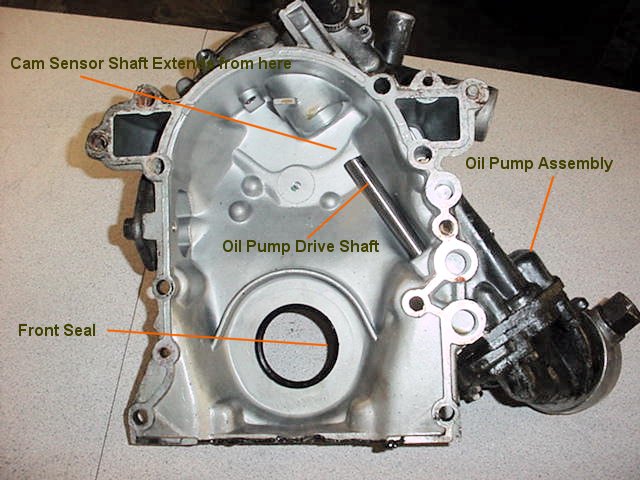
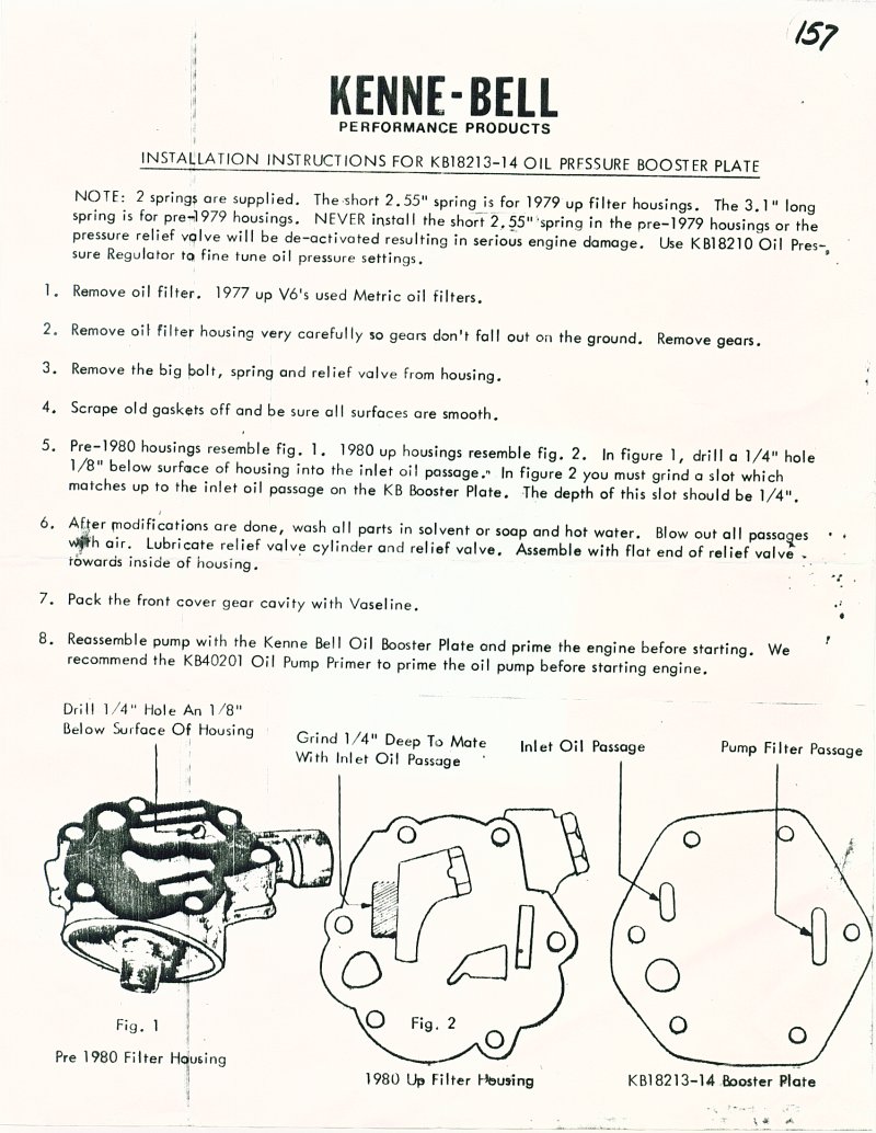
Looking at the rear of the front cover we see the external oil pump assembly and the shaft from the oil pump drive shaft emerging into the cover. This shaft is driven by the cam sensor which mounts on top of the cover and engages the top of the pump drive shaft. In turn, the cam sensor is driven by the gear on the nose of the cam shaft.
Note that the actual pump does not sit immersed in the oil pan, but, is located above the oil level. This is what makes the Buick more difficult to prime. It will simply not suck oil into the pump and thru the system by merely spinning the drive shaft after the cam sensor is removed.
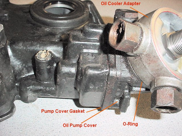
This is a close up of the oil pump gear housing, pump cover, and oil cooler adapter. The O-Ring is often a source of a leak and most vendors carry slightly larger o-rings which improve the seal. The threaded tube emerging from the adapter is what the filter screws onto. This is the piece that is replaced when one buys a "biggy" filter kit. Simply put a wrench on the nut and remove the factory threaded tube which is metric for one that has standard threads. This is a good time to replace the o-ring.
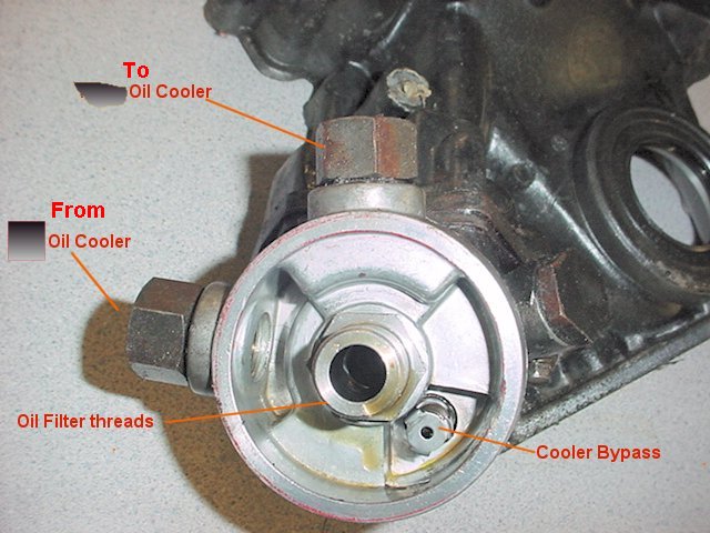
Here we look straight at the oil cooler adapter. Note that cooler bypass is not the same as the oil filter bypass. The large bolt (unlabelled) to the right hand side of the adapter covers the high pressure bypass valve that we shall see below.
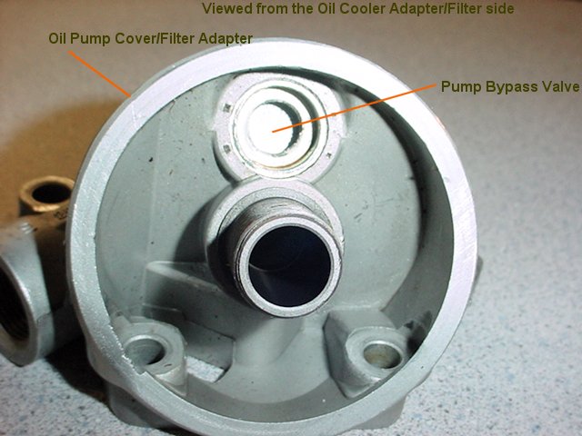
When we remove the oil cooler adapter we see the pump cover/filter adapter. Note the bypass valve (see the following note) that allows the filter to be bypassed when the pressure differential thru the filter exceeds the bypass valve spring pressure. This may happen on cold start ups or when the filter is plugged with trash. This is the reason that we don't rev engines when the oil is cold and pressure is high. Some advocate plugging this bypass with a dime or small expansion plug (Dorman plug p/n 555-107). Note, in this picture, the bypass valve has been removed and we are looking at a plug that was used to block the passage after the original valve assembly was removed. This may work on race cars with lighter weight oil, or in warmer weather. On the other hand, it has been known to collapse the filter media and/or blow the sealing ring out of the filter. This happened twice in November. Once on a car in Florida and the second was reported in Arkansas. Both engines were lost. Over the years such failures have often been reported. I suspect both had filters installed that had no internal bypass valve. Most filters don't.
Now, if you want to achieve full filtration by blocking the bypass, you must use a filter that has an internal bypass to replace the factory bypass that you plugged. The factory bypass apparently has a very weak spring that allows unfiltered oil to be circulated when the differential pressure resulting from the reluctance of the filter to allow thick, cold oil to penetrate the filter media without undue resistance. The factory spring is reported to be in the range of 4 psi which is very little. This allows a lot of oil to be bypassed until the oil warms up. One note, the original bypass valve assembly does not have to be removed if the plug is fitted over the plunger assembly.
If using the stock filter arrangement, the Fram Racing filter HP-11 has a 22# bypass which is much better...it also has an antidrainback valve inside.
If using the "Biggie" filter adapter, the Fram Racing filter HP-2 is reported to fit and has the same bypass and antidrainback.
If using the PTE Turbosaver remote filter, then a Baldwin B279 or a Fram HP4 will work. the Baldwin has a 20# bypass as opposed to the 22# in the Fram.
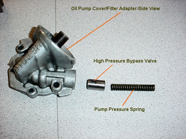
Here is a picture of the oil pump cover/filter adapter removed from the cover. Note the high pressure bypass valve and the spring that determines the bypass pressure. There is no need to have oil pressure in excess of 70 psi in a daily driver. Increasing this pressure merely wastes horsepower and increases the load on the cam sensor and front cam bearing. The yellow spring that comes in most kits is often suggested.
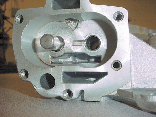
When the pump cover/filter adapter is removed, we would normally see the pump gears sitting in the cavity of the pump body. In this picture, the gears have been removed in order to show the cavity.
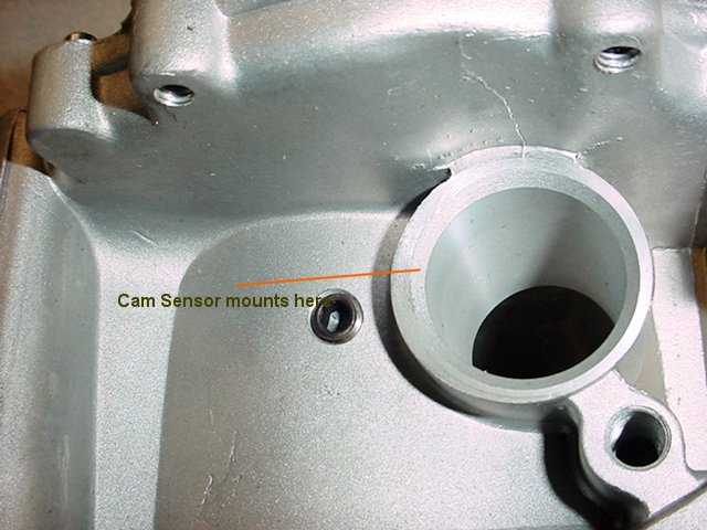
This is a picture of the top front of the cover where the cam sensor is mounted. Note the allen bolt next to the mounting hole. This must be Locktited in place so that it cannot fall into the cover, or, unscrew and allow water or trash into the front cover.
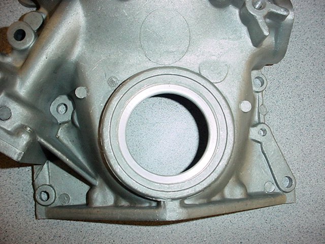
This is a picture of the front crankshaft seal area at the bottom of the cover taken from the front of the cover.
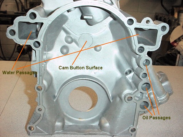
This is the rear side of a new front cover. Care should be taken to examine the cover carefully on the inside and all casting flash should be removed including the area the cam button rides. It's a good idea to check for cracks in the cover and pump cavity as well.
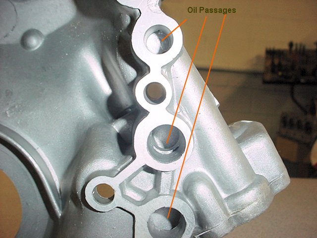
It's hard to take a picture of the oil passages, but, it is absolutely necessary to examine the passages and remove any casting flash which might prevent or minimize oil flow. It is extremely common for the intersection of some passages to be blocked by casting flash and it is frustrating to assemble an engine and be unable to prime the oil system or have low pressure/volume due to this blockage. It's a good idea when cleaning out the flashing to radius the intersections of intersecting passages to improve the flow of oil around corners. Get out your Dremel tool.
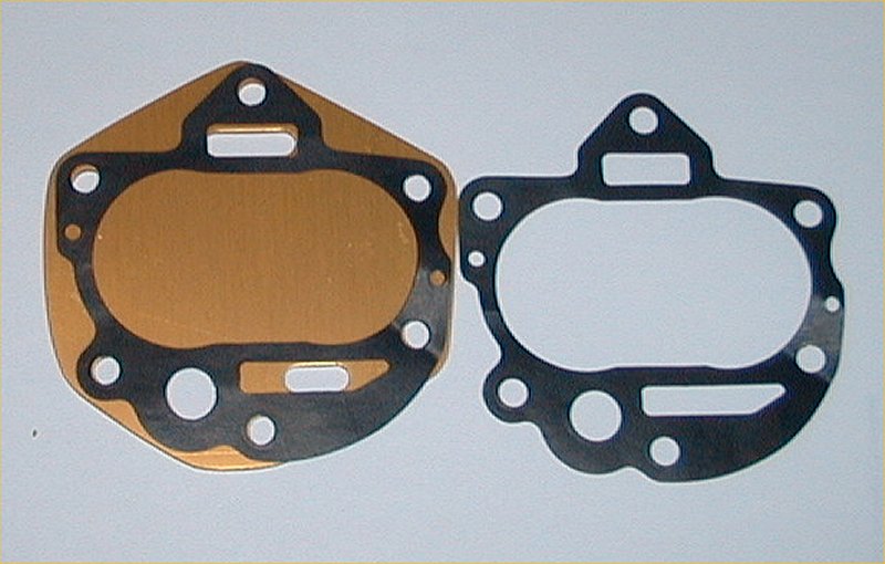
Also, check the gasket between the cover and block and be sure that the holes match up with the passages, and, that the gasket covers all the sealing surfaces..
The correct GM gasket is #12337540. Be sure you get this part number as the counterman does not always know the difference.
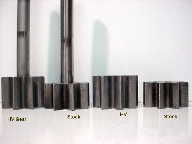
Here are pictures of both high volume and stock pump gears. The high volume gears are taller and present more area to the oil. In a high volume cover, they simply drop straight in. In a standard cover, a spacer is required between the pump cavity body and the pump cover/filter adapter.
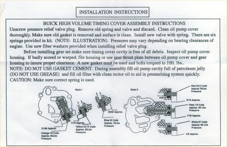
Go here for instructions on setting up the oil pump.
Above is a Kenne-Bell high pressure plate. It goes between the pump cover and the pump cavity. As per the instructions below, it takes a bit of Dremel work on the pump cover as shown.
There is also a replacement thrust plate that goes between the cover and the body to provide a smooth surface for the pump gears to ride against. Never assemble a pump and use a cover that is grooved as it will hurt the oil pressure as it artificially increases end clearance.